Rim construction explained
A rim always consists of a rim base with bead seats, a disc and a bolt pattern that determines the connection to the hub. Dimensions such as rim width, diameter, bolt pattern (PCD) and offset (ET value) form the basis of every product specification.
In this article, we clearly and practically explain how a rim is constructed, which dimensions you will encounter and what they mean in practice for stability, fitment and application.
.jpg)
Basic rim construction
Every rim consists of three main components that together form the structure on which the tyre is mounted:
- Rim base: including bead seats where the tyre bead is secured
- Disc (wheel disc): the central part with bolt holes that connects to the hub
- Flange edges: keep the bead under tension and prevent it from slipping under load
Truck rims typically have fixed discs for maximum stability and brake clearance. Agricultural rims may feature adjustable discs to modify track width. Earthmoving rims are often heavy-duty and reinforced to withstand high torsional loads.
The combination of width, diameter, bolt pattern and offset ultimately determines whether a rim is technically suitable for a vehicle.
Flange edge
The flange edge ensures that the tyre bead remains under tension and is therefore a crucial part of the rim construction. This is especially important for heavy truck axles, agricultural machines operating at low pressure and earthmoving equipment exposed to high torsional forces.
The three key flange dimensions:
- A — Inner diameter of the rim
- B — Width between the flanges
- C — Flange height
These dimensions are essential for correct tyre fitment, stability and airtight sealing. In technical specifications, these values are almost always included to guarantee compatibility.

Rim cross-section
Diameter of a rim
- G = Hub bore diameter (centre bore)
- S = Bolt pattern (PCD) and number of bolt holes
- N = Stud pattern diameter and number of studs
- W = Wheel offset (disc position, not flange)
- D = Bolt hole diameter and type of hole
- E = Additional holes for wheel weights
- B = Outer diameter of the disc
Rim width & diameter: sizing per vehicle type
Rim width determines how the tyre sits and performs. A rim that is too wide stretches the tyre, while a rim that is too narrow causes deformation and increased wear.
The rim diameter must exactly match the tyre diameter. In practice, diameter selection is strongly dependent on the sector:
- Truck: typically 22.5", aligned with brake components and load index requirements
- Agriculture: various sizes for low pressure, row crop or transport applications
- Earthmoving: heavy-duty diameters for load capacity and stability
Rim size is always expressed as width × diameter, for example 14×19.5 or 22.5×9.00.
ET value and wheel position for truck, agriculture and earthmoving
The ET value (offset) determines the radial position of the disc relative to the centreline of the rim. This affects track width, steering geometry, brake clearance and bearing load.
Application by sector:
- Truck: correct ET is crucial for brake clearance and stability
- Agriculture: used to adjust track width for row spacing
- Earthmoving: prevents uneven forces and supports high torsional loads
More information:
ET value of a rim
Bolt pattern (PCD): bolt configuration and fitment
The bolt pattern (PCD) defines the number of bolt holes and the diameter of the pitch circle, for example 10×335 or 8×275. This determines whether a rim fits correctly on the hub and centres properly.
Measurement methods
- For 4/6/8/10 bolts: measure centre-to-centre between opposite holes
- For 5 bolts: measure from the outer edge of one hole to the centre of the opposite hole
Sector examples:
- Truck → 10×335 and 10×285.75 are common
- Agriculture → varies depending on OEM and application
- Earthmoving → often reinforced and heavy-duty
Rim cross-section: technical dimensions
A technical cross-section provides a complete overview of all relevant rim dimensions. These measurements are essential for fitment checks, brake clearance, hub compatibility and load capacity assessment.
Key cross-section dimensions:
- G — Hub bore diameter
- S — Pitch circle diameter (PCD) + number of bolt holes
- N — Stud circle diameter + number of studs
- W — Disc offset depth
- D — Bolt hole diameter and finish
- E — Additional mounting holes
- B — Outer diameter of the disc
Together, these parameters form the technical blueprint of every rim.
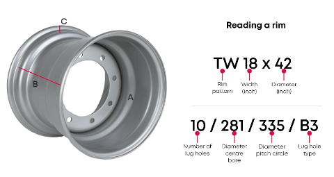
Reading technical specifications: width, diameter, PCD and ET
Rim product descriptions almost always follow the same structure. Example:
14×28 – 8×275 – ET+50
This means:
- 14 inch width
- 28 inch diameter
- Bolt pattern 8×275
- Offset +50
This combination determines whether the rim fits mechanically and functionally on a specific vehicle. For trucks, tractors and earthmoving machines, this prevents incorrect track width, excessive bearing load or interference with brake components.
Frequently asked questions about Galileo CupWheel
How do I determine if a rim fits technically?
By checking rim diameter, rim width, PCD, ET value and hub bore diameter in combination with OEM specifications.
Why does rim construction differ by sector?
Trucks require stability and brake clearance, agricultural machines need adjustable track width and low-pressure capability, while earthmoving equipment requires high torsional strength.
Is a different ET value acceptable?
Only within OEM tolerances. Deviations can affect stability and bearing load.